DIY Arc Welder
Andrew's Project Portfolio
Project Schmelty is an 80 amp Shielded-Metal arc welder (SMAW) built on the cheap out of mostly recycled materials.
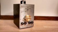
Powered by three hand-rewound microwave oven transformers, Schmelty lives a stylish life inside of what may possibly have been a speaker housing. Power output is managed by an oversized Silicon Controlled Relay for pulse width modulated current.
I'll start with how I picked the wiring, then how to keep generated electrical noise from filtering back into the house, how to keep the thing cool by design, and how to control the power output. I stumbled on a few more issues while assembling and using the welder, which you'll find in the second section.
Highlights
Basics
Knowing that $ V=IR $, the best I could hope to get out of a 120v outlet with a 20A breaker would be $ 20 \cdot 120=2400 Watts $. I also figured that hand rewinding a transformer wouldn't get me close to the ~86% efficiency an AC transformer is expected to operate at, I'd likely be at 75% efficiency. So at worst theoretically,I expect to get $ 2400W \cdot $
As current increases, so must the diameter of the wiring. However, I also needed a minimum of 30V out of the welder to effectively weld based on documents about welding I found. If the wiring were too large, I wouldn't get the voltage necessary, but I'd have plenty of current. Too small and I'd have plenty of voltage but the current might destroy the wiring. 12V seemed right, and a forum on DIY tesla coils indicated that the primary coil on the transformers I had were wrapped about 200 times. An ideal transformer has $ turn_{ratio}=Turns_{primary}/Turns_{secondary}=Volts_{primary}/Volts_{secondary} $. So finally, $ Turns_{secondary}=200 \cdot 12V/120V=20 wraps$. Since $2400W/36V=66.7A$, I needed to use 8 AWG wire in rewinding each transformer.
Noise Filtration
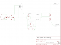
Because arcs are notorious (and in fact purposely used) for creating electrical noise, a simple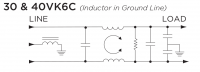 high-current LCR bandpass filter before energy reaches the transformers keeps the noise from traveling back into the building's power system. I chose the Tyco 40VK6C to handle this filtration.
DC Welding
Alternating current is generally the only option when using a cheap welder, and its constant oscillation between positive and negative voltage at 60Hz makes for ugly welds.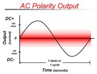 I installed connectors on the front for both AC & DC because converting the waveform incurs losses, and on an already small welder this may lead to situations where I need that little bit of extra amperage.
To actually convert the waveform from AC to DC, I installed a 1000V 100A Bridge Rectifier to convert the 82A max output to DC. This rectifier features an aluminum heatsink integrated into its body, to ensure that it could handle the full load it was designed for, but this welder couldn't ever reach.
Current Control
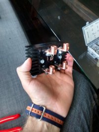
To tune the output current to the thickness of whatever material I happened to be working on required that I integrate a control circuit. I based mine on Youtube user MindToMachine's design which uses the appropriately sized IRKT91-12 Silicon-control 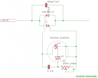 relay to pulse power to the transformer primaries. The longer the pulse, the higher the power output.
In assembling Project Schmelty, I paid careful attention to balancing the design choices for a fully-functional & reliable well-cooled system which would also catch your eye.
Exterior
Case
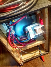
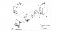
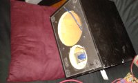 The case is made of 1/2 in [12.7mm] thick MDF. My Solidworks mockup indicated that I'd have enough room to fit all the other components, though fitting my hands inside for the wiring stage might be a little bit of a struggle. I drilled holes as necessary to support the countersunk screws which hold various power components. Because the case is meant to isolate and protect the power components from the world, the transformers are all grounded to ensure that no voltage could accidentally escape to the outside using the bolts.
Face Plate
I didn't want to add a bunch of ugly ventilation holes to the face plate, instead opting to provide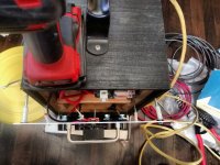 enouch space between the case and the faceplate for cool air to make its way in along the sides without obstruction. This is accomplished by using nylon spacers and long countersunk steel screws. Hot air is pushed out along the bottom edges.
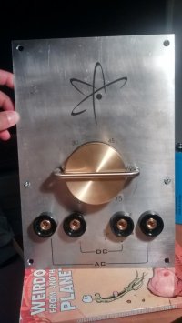 I made decals using my laser printer with laser decal paper and set them on the faceplate, using Microset to enhance durability and adhesion. As a result, the welder looks professionally made and is straightforward to use.
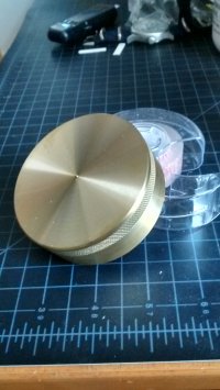
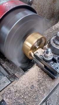
The control knob is made out of solid brass, turned by hand on my school's lathe to reduce weight, knurled for grip and tapped with a set-screw to attach the knob to the potentiometer.
Wiring
I chose Romex solid wiring as the supply wire from the house to the welder because it has three conductors (Hot, neutral & ground) in one cable at the ampacity levels I need.
Connectors
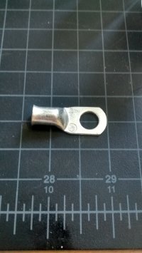 Normally when working on electronics, I solder my connections together. However, at the current levels present in this welder, solder would melt, so I needed to use physical connection methods such as crimps and bolts. These facilitate thermal expansion when lots of current is flowing through the individual connections and make for a solid connection in all conditions.
Testing
To test just how far off any calculations and associated estimates were, I made a simple water-cooled loop of copper to run the current through while my Fluke clamp ammeter was reading the average continous current at a few different positions on the control knob.
Welds in AC are a little messy, but I suspect it's because I am not an experienced welder. Nothing a file can't take care of.
DC welds come out a lot nicer, I even managed to tack weld some thin aluminum together for a friend which was surprising.
Lessons learned
For the future, I will need to change the prime supply line (currently solid conductor Romex) with something flexible, as Romex has the ampacity requiremnt but is not flexible and will likely fail after being subjected to enough twists and bends as the regular power cords for other appliances usually are.
There's also a lot of work being done with IGBTs (Insulated Gate Bipolar Transistor) which allows one to replace the heavy transformers with solid state switching circuits and much smaller transformers. Less energy gets lost to the air as the switching frequency is a heck of a lot higher, up to 20kHz apparently. I wonder how difficult they are to DIY?..